The pressure gauge only needs an opening to take pressure, and compared to the plug-in gauge, there is more space for selecting the source point. In order to facilitate maintenance, a valve must be installed at the source point. The primary valve is generally a needle globe valve or a needle ball valve. If it is flanged, the primary valve is usually a gate valve.
1 Installation of pressure source components
1.1 Installation conditions
There are two types of pressure source components. One type is a short section of pressure, which is a short tube. Used to weld pressure points and pressure valves on pipelines. One type is external threaded pup joints, that is, one end has an external thread, generally KG1/2", one end has no thread. After determining the pressure point on the pipe, weld the end without thread to the pressure point on the pipe (vertical opening ), the threaded end can be directly screwed on the internal threaded stop valve (primary valve). No matter which form of pressure is used, the installation of the pressure source component must meet the following conditions:
1) The installation position of the pressure taking part should be selected where the medium flow rate is stable.
2) When the pressure source part and the temperature source part are on the same pipe section, the pressure source part should be on the upstream side of the temperature source part.
3) When welding pressure source components, pay attention to the end not exceeding the inner wall of the process equipment or process pipeline.
4) When measuring the pressure of turbid media with dust, solid particles or sediment, the source component should be installed tilted upward. The horizontal process pipeline should be installed downstream at an acute angle.
5) When measuring the pressure of liquid, steam or condensable gas with a temperature higher than 60℃, the source part of the pressure gauge installed on the spot should be equipped with a ring or U-shaped condensing bend. Figures (a) and (b);
6) When measuring pressure with severe fluctuations (such as the outlet pressure of pumps and compressors), a needle valve and a buffer should be installed before the pressure gauge, and a damper should be installed if necessary. As shown in figure (c);
7) When measuring the pressure of a medium that is viscous or easy to crystallize, an isolation tank should be installed on the pressure taking device so that the tank and the pressure guiding tube are filled with isolation liquid, and heat preservation measures can be taken if necessary. As shown in figure (d);
8) When measuring the pressure of the dust-containing medium, it is best to install a dust collector after the pressure taking device, as shown in figure (e).
1.2 Pressure tube
1) The pressure guiding tube where the pressure transmitter is installed should be as short as possible and have as few elbows as possible.
2) Selection of pressure guiding pipe and pipe diameter: In-situ pressure gauges generally use Φ18*3 or seamless steel pipes. Φ18*3 is preferred for pressure gauge bend or condensation bend, and Φ14*2 seamless steel pipe is usually used for pressure guiding tube. High-pressure pipelines with pressure higher than 22MPa should use Φ14*4 or Φ14*5 high-quality seamless steel pipes. On pipelines with a pressure lower than 16MPa, the pressure guiding tube sometimes uses Φ18*3, but it is difficult to form at a time when it is cold simmered, and it is generally not commonly used. For low pressure or low pressure dust gas, 1" water gas pipe is often used as the pressure guiding pipe.
3) When the pressure guiding tube is laid horizontally, it must have a certain slope. In general, maintain a slope of 1:10 -1:2. In special circumstances, the slope can reach 1:50. When the medium in the pipe is gas, there should be a drain device (usually a drain valve) at the lowest position of the pipe. When the medium in the pipe is liquid, an exhaust device is installed at the highest point of the pipeline (usually an exhaust valve is installed, and some gas collectors are also installed).
1.3 Pressure measurement by isolation method
1) The pressure of corrosive and viscous media is measured by the isolation method, which is divided into two types: air blowing method and liquid flushing method. The air blowing method is used for isolation and is used to measure the pressure of corrosive media or solid particle suspensions. The flushing method is used for isolation and is suitable for viscous liquids and suspensions containing solid particles.
2) In the pipeline that uses the isolation method to measure pressure, there should be a drainage device at the lowest position of the pipeline. There are two ways to infuse spacer fluid. One is to use compressed air to lead to a special isolation liquid tank, and inject it from the drain valve at the lowest part of the pipeline to facilitate the discharge of air in the pipeline until the top valve is filled. This method is especially suitable for the situation where the transmitter is installed far from the pressure point. Another method is that when the transmitter is installed near the pressure point, the isolation fluid is poured from the top wire of the isolation container. In order to easily remove the bubbles in the pipeline, the first method is better.
1.4 Gasket
The gaskets for pressure gauges and pressure transmitters are usually tetrafluoroethylene gaskets. For oil products, gaskets made of oil-resistant rubber asbestos boards can also be used. Steam, water, air and other non-corrosive media, gasket materials can choose ordinary asbestos rubber sheet. Saturated steam and superheated steam use red copper pad or graphite pad, etc.
1.5 Installation location
The installation position of the local pressure gauge must be easy to observe. The pressure gauge at the pump outlet must be installed before the outlet valve.
2 Pressure pipeline connection method and corresponding valve
2.1 Classification by valve and pipe joint
1) The piping connection system mainly adopts ferrule valve and ferrule or pipe joint. It is characterized by high temperature resistance, good sealing performance, convenient loading and unloading, and no hot welding is required.
2) The pipeline connection adopts external thread stop valve and pressure cushion pipe joint, which is a common connection form in chemical industry.
3) The pipeline connection system adopts external thread stop valve, internal thread gate valve and pressure cushion pipe joint, which are commonly used connection forms in oil refining systems.
---The above three methods can be used at will, but when possible, use the card sleeve connection form as much as possible.
2.2 Commonly used matching valves
1) The pressure meter needs to install a valve.
2) If it is flanged, the primary valve is generally a gate valve.
3) It is not a flange connection, the primary valve is generally a needle-type globe valve; if the medium is easy to block, a needle-type ball valve is generally used; for high temperature and high pressure occasions, a valve should be a welded globe valve made of high temperature resistant material. The two-way valve and the sewage valve usually adopt the needle valve of J23W-160, and the pressure rating and material are selected according to the site conditions.
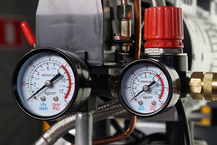
3 Installation of pressure gauge
The pressure port on the horizontal pipeline is generally led out from the top or side to facilitate installation. When installing a pressure transmitter, when the pressure guiding pipe is led far away, the requirements for the orientation of the pressure on the horizontal and inclined pipes are as follows: When the fluid is liquid, in the lower half of the pipe, within the angle range of 45° with the horizontal center of the pipe, Do not take pressure at the bottom; when the fluid is steam or gas, it is generally the upper half of the pipe, within the range of 0-45° with the horizontal centerline of the pipe.
Commonly used pressure gauge measuring pipeline connections are shown in the above figure (a) ~ (e).
The installation methods of pressure transmitters are basically the same, which are divided into bracket installation, incubator and protective box installation, and direct installation. There are two types of bracket installation, one is the bracket on the wall and the other is the bracket on the ground. These two elevations are generally: +1.20 meters ~ +1.50 meters, keep the elevation of the transmitter indicator: +1.50 meters. If these two installation methods are in the same workshop or the same workshop, the elevations must be the same, and the transmitters (including differential pressure transmitters, etc.) installed on the wall and the ground bracket must be the same.